T9X mod to use Flysky module, Frysky module and DSMX module

Re: T9X mod to use both Flysky module and Frysky module
Actually the picture isn't the final one - I had my nice little 3.3V regulator in the bind button board's end pins, but this one couldn't take the current spikes from the DSM module. I since then removed it and installed the one from the DX4e. I don't have a photo, need to take one tonight. As it's SMD, the result is much less clean 

Re: T9X mod to use both Flysky module and Frysky module
Re: T9X mod to use both Flysky module and Frysky module
I explained it to you in the PM...
You need BOTH the 7805 AND the 5V -> 3.3V regulator that is in the DX4e, cascaded.
In my case, the 7805 was already on the bind board from the stock module, so all I needed was solder the DX4e's reg inline.
You need BOTH the 7805 AND the 5V -> 3.3V regulator that is in the DX4e, cascaded.
In my case, the 7805 was already on the bind board from the stock module, so all I needed was solder the DX4e's reg inline.
Re: T9X mod to use both Flysky module and Frysky module
Ah, I misunderstood that 7805 is what I needed in place of the 5->3 volt regulator. Well, will find some use for it some time. 
But I want to see your final pics when done. don't worry about cleanliness, I am half blind any way.
But I want to see your final pics when done. don't worry about cleanliness, I am half blind any way.
Re: T9X mod to use both Flysky module and Frysky module
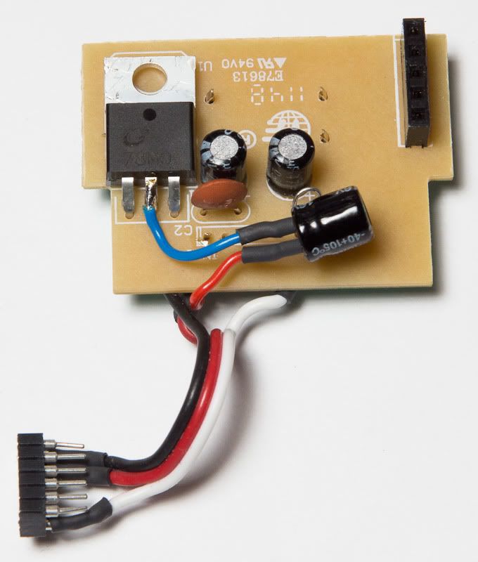
The 220uF capacitor is also taken from the DX4e and connected at the output of the 3.3V Vreg (in parallel to the DSM module).
Re: T9X mod to use both Flysky module and Frysky module
Wow , that is a total rearrange of circuit there from previous one. There are some wires I can't see clearly where they go. ONce I get my DX4e module out and has all the components needed I will check again with you about those unclear connects.
With this circuit, did you get all the surge problem solved?
With this circuit, did you get all the surge problem solved?
Last edited by kaos on Sat Apr 07, 2012 12:19 am, edited 1 time in total.

Re: T9X mod to use both Flysky module and Frysky module
Well, I guess it's your faultkaos wrote: don't worry about cleanliness, I am half blind any way.
next time when you ask for something, ask for the best that you can get
My er9x/Ersky9x/eepskye Video Tutorials
https://www.youtube.com/playlist?list=PL5uJhoD7sAKidZmkhMpYpp_qcuIqJXhb9
Donate to Er9x/Ersky9x:
https://www.paypal.com/cgi-bin/webscr?cmd=_s-xclick&hosted_button_id=YHX43JR3J7XGW
https://www.youtube.com/playlist?list=PL5uJhoD7sAKidZmkhMpYpp_qcuIqJXhb9
Donate to Er9x/Ersky9x:
https://www.paypal.com/cgi-bin/webscr?cmd=_s-xclick&hosted_button_id=YHX43JR3J7XGW
Re: T9X mod to use both Flysky module and Frysky module
I am not going to worry about that. Kilrah is working on that I am sure. Swedish you know! 
Re: T9X mod to use both Flysky module and Frysky module
Swedish?? 
My er9x/Ersky9x/eepskye Video Tutorials
https://www.youtube.com/playlist?list=PL5uJhoD7sAKidZmkhMpYpp_qcuIqJXhb9
Donate to Er9x/Ersky9x:
https://www.paypal.com/cgi-bin/webscr?cmd=_s-xclick&hosted_button_id=YHX43JR3J7XGW
https://www.youtube.com/playlist?list=PL5uJhoD7sAKidZmkhMpYpp_qcuIqJXhb9
Donate to Er9x/Ersky9x:
https://www.paypal.com/cgi-bin/webscr?cmd=_s-xclick&hosted_button_id=YHX43JR3J7XGW
Re: T9X mod to use both Flysky module and Frysky module
He's American, you know, so it's pretty normal
Yep no problem, I've been flying a few hours with it so far and no issues.kaos wrote:With this circuit, did you get all the surge problem solved?
Re: T9X mod to use both Flysky module and Frysky module
OH, no. Swedish is flying with a Medusa head. 

Re: T9X mod to use both Flysky module and Frysky module
The only Swede here is me , right???
To support the forum:
https://www.paypal.com/cgi-bin/webscr?cmd=_s-xclick&hosted_button_id=82QKZZN5ZC8JE
To support ER9X:
https://www.paypal.com/cgi-bin/webscr?cmd=_s-xclick&hosted_button_id=YHX43JR3J7XGW
https://www.paypal.com/cgi-bin/webscr?cmd=_s-xclick&hosted_button_id=82QKZZN5ZC8JE
To support ER9X:
https://www.paypal.com/cgi-bin/webscr?cmd=_s-xclick&hosted_button_id=YHX43JR3J7XGW

Re: T9X mod to use both Flysky module and Frysky module
Not quite the only Swede.
But I am not all that active. Although I have translated open9x and companion9x to Äran och Hjältarnas Språk (i.e. Swedish to the rest of you)
But I am not all that active. Although I have translated open9x and companion9x to Äran och Hjältarnas Språk (i.e. Swedish to the rest of you)
Re: T9X mod to use both Flysky module and Frysky module
Ah, all Swedes /Swiss popped up. Well, Puma Swede beats you all.
Re: T9X mod to use both Flysky module and Frysky module
OK, 1st step toward the making of swappable DSMX module.
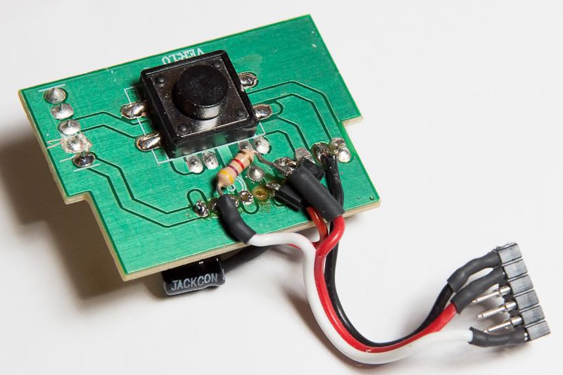
made a soldering tip from a 2.5 mm diameter copper wire and it worked well for desoldering the Flysky antenna from module board and pulled the reset button board. Looks like nothing was burned.
tomorrow will be the time to get the DX4e module out of the Tx.
made a soldering tip from a 2.5 mm diameter copper wire and it worked well for desoldering the Flysky antenna from module board and pulled the reset button board. Looks like nothing was burned.
tomorrow will be the time to get the DX4e module out of the Tx.
- Attachments
-
- here is the reset button baord
-
- the DIY soldering tip - 2.5 mm copper wire (great advice from Bill516)
-
- antenna desoldered from module board
Re: T9X mod to use both Flysky module and Frysky module
Kilrah: I am getting ready to put the module together. But I could not find a 220 uF capacitor of that size as shown in your pic. are you sure it is 220 uF not 22 uF? 220 uF is huge.
Re: T9X mod to use both Flysky module and Frysky module
Hmm not 100% sure, but I grabbed it from the DX4e, see attached pic for location.
A 6.3V rated 220uF cap shouldn't be much bigger than that.
A 6.3V rated 220uF cap shouldn't be much bigger than that.
- Attachments
-
Re: T9X mod to use both Flysky module and Frysky module
yes, that is the voltage regulator, what i am saying is the capacitor between te 78m50 and the voltage regulator. or are you saying that red circle back side is the capcitor?
Re: T9X mod to use both Flysky module and Frysky module
That.kaos wrote:are you saying that red circle back side is the capcitor?
I have connected the cap on the output of the 3.3V Vreg.
Re: T9X mod to use both Flysky module and Frysky module
yep, now I see it. it is at the back of that red circle and it is 220uF. boy, this one is a lot smaller than the ones I saw today at radio shack. Back to desoldering now.
Re: T9X mod to use both Flysky module and Frysky module
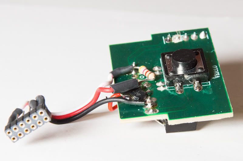
OK, look what I have now.
question. Is there an easy way check whether the 220 uF capacitor and the 3.3 Volt regulator is in good condition? (not burned out by my desoldering) Before I solder them all together.
question. Is there an easy way check whether the 220 uF capacitor and the 3.3 Volt regulator is in good condition? (not burned out by my desoldering) Before I solder them all together.
- Attachments
-
-
Re: T9X mod to use both Flysky module and Frysky module
Nope, not really. However, once you've soldered everything together and have your 3 wires ready to be connected to the DSM module, DO check the voltage is correctkaos wrote:Is there an easy way check whether the 220 uF capacitor and the 3.3 Volt regulator is in good condition?
Re: T9X mod to use both Flysky module and Frysky module
OK, so if I see smoke, then i will know.
now this is the critical questions:
1. the capacitor is polarized or not. I remember , long time ago, some are some aren't . this 220 uf is or not. if it is which end is which, how to tell?
2. in your 'final version' of the circuit, some connections I can't tell for sure.
here is what I can get from the pics:
blue wire from mid pin of 7850 to capacitor then through red wire to the back tab of the 3.3 reg.
the right tab of the 3.3v reg is soldered onto the middle row 4th dot from the right of the reset board. the left tab of 3.3 reg is soldered to the 6th dot from the left (bottom row)
the middle tab of the 3.3 v reg is soldered to the 4.7K resistor and the red wire to 2nd pin of the connector
the white wire is solder to the other end of the 4.7K resistor and to the 2nd dot from the left(bottom row) (which should be one of the diode's lead too), and goes to the 6th pin of the connector.
the black wire goes from the 2nd dot of the middle row (which is also the middle pin of the 7850) to the 1st pin of the connector.
Did I confuse you? That is how your circuit/pic confused me.
now this is the critical questions:
1. the capacitor is polarized or not. I remember , long time ago, some are some aren't . this 220 uf is or not. if it is which end is which, how to tell?
2. in your 'final version'
here is what I can get from the pics:
blue wire from mid pin of 7850 to capacitor then through red wire to the back tab of the 3.3 reg.
the right tab of the 3.3v reg is soldered onto the middle row 4th dot from the right of the reset board. the left tab of 3.3 reg is soldered to the 6th dot from the left (bottom row)
the middle tab of the 3.3 v reg is soldered to the 4.7K resistor and the red wire to 2nd pin of the connector
the white wire is solder to the other end of the 4.7K resistor and to the 2nd dot from the left(bottom row) (which should be one of the diode's lead too), and goes to the 6th pin of the connector.
the black wire goes from the 2nd dot of the middle row (which is also the middle pin of the 7850) to the 1st pin of the connector.
Did I confuse you? That is how your circuit/pic confused me.
-
GrootWitbaas

- Posts: 358
- Joined: Tue Dec 27, 2011 8:57 pm
- Country: -
- Location: Germany
Re: T9X mod to use both Flysky module and Frysky module
for the cap I can help, yes it is polarized, you can see from the marking.
General trouble maker and wannabee Dev
Re: T9X mod to use both Flysky module and Frysky module
Thx Groot. I got it. Now just wait Kilrah to sort out his Medusa head creation. i am all ready to go. After he read what I wrote, his head is probably like that too.
-
cre8tiveleo

- Posts: 1434
- Joined: Tue Dec 27, 2011 6:13 pm
- Country: -
- Location: Ontario,(GTA North)
- Contact:
T9X mod to use both Flysky module and Frysky module
Kaos, read the thread on new servo limits...
New feature: ppm servo settings... Or something like that
---
I am here: http://tapatalk.com/map.php?vbqhrs
New feature: ppm servo settings... Or something like that
---
I am here: http://tapatalk.com/map.php?vbqhrs
-
cre8tiveleo
- Posts: 1434
- Joined: Tue Dec 27, 2011 6:13 pm
- Country: -
- Location: Ontario,(GTA North)
- Contact:
Re: T9X mod to use both Flysky module and Frysky module
While waiting Kilrah's answer/clarification. I looked into the 5.5 V and 3.3 v chip diagram. and what is going on with the electronic industry. For LM78m05 5.5 chip the GND is the middle pin but the the 3.3 chip (LD1117S33) the GND is the left pin (when pins are facing down). Engineers surely knows how to make things complicated.
No wonder I was so confused how kilrah wired those reset button board and the 3.3 volt reg. But , Kilrah, still need your clarification for final soldering.
No wonder I was so confused how kilrah wired those reset button board and the 3.3 volt reg. But , Kilrah, still need your clarification for final soldering.
Re: T9X mod to use both Flysky module and Frysky module
Ook.
Let's say the pin on the left is pin 1.
The diode is between pin 1 and 2. The marking towards pin 1. The diode's lead on pin 2 is left a bit longer and bent out. The white (signal) wire AND one leg of the resistor get soldered to it.
Pin 3, 4, 5 are unconnected.
Pin 6 is +5V, and receives the "right" leg of the 3.3V regulator.
The middle leg and tab of the regulator are lifted and mustn't touch anything (they're both 3.3V out). The other leg of the resistor is connected there, along with the cap's positive and the red wire (3.3V supply to the module).
The regulator's left leg is soldered somewhere on the large ground area on the right of the PCB, along with the cap's negative and the ground wire to the module.
Hope it clears it up