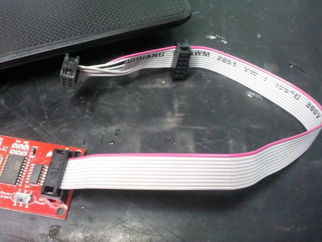
im getting ready to flash my newly arrived t9x with the sparkfun pocket avr.
the only thing that stops me from starting is that i cant find the wire location with the stock grey connector that came with the pocket avr.
thanks for helping me out

What wire you are talking about and what about it's location??agusta600gt wrote:hello everyone...i hope im on the right place to post this thread.
im getting ready to flash my newly arrived t9x with the sparkfun pocket avr.
the only thing that stops me from starting is that i cant find the wire location with the stock grey connector that came with the pocket avr.
thanks for helping me out

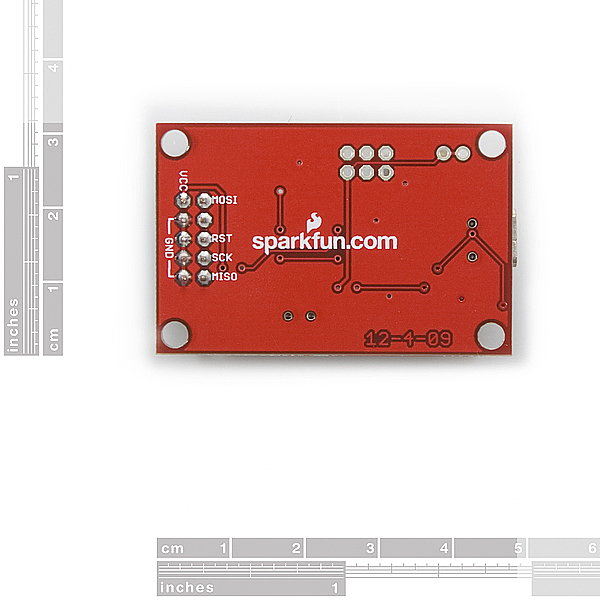

agusta600gt wrote:...all the wires are grey except one that is red.where do i solder the red one...and wich one goes where
