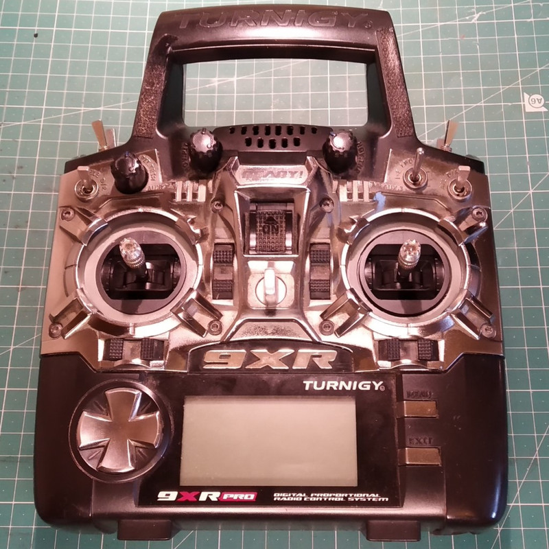
I apologise for reopening this long-dead thread, but I thought I would share my experience of installing Jumper Gimbals on my 9XR Pro with ErSky9x/ErskyTx.
The Jumper gimbals the same Allegro A1392 Hall effect sensors that are used in the FrSky M9 gimbals and have ball bearings, but are more compact so can be installed without making any modification to the transmitter. They are also about half the price of the FrSky gimbals.
Disclaimer:
Modifying your radio is risky, so do not attempt this unless you know what you are doing. I only post this information to document the modifications that I have made to my own transmitter, and it is not intended to encourage you to do the same. You do so only at your own risk and I take no responsibility for any resulting damage to either the transmitter or the gimbals. I also take no responsibility for any damage, injuries, losses or claims whatsoever resulting from the use of, or any failure of, a modified receiver.
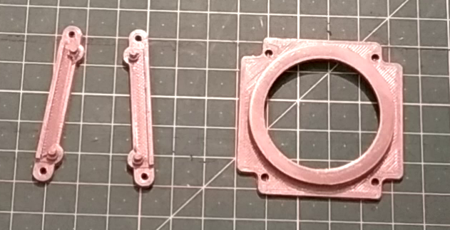
The gimbals I used were are designed for use with Jumper T8SG V2 / T8SG V2 Plus / T12 /T12 Plus radios. They can be easily obtained from AliExpress and other internet sites. In order to fit them into the Turnigy 9XR designed 3D printable adapter brackets. I have uploaded the design, along with instructions on how to mount the gimbals physically into the transmitter, to thingiverse here:
https://www.thingiverse.com/thing:4896110
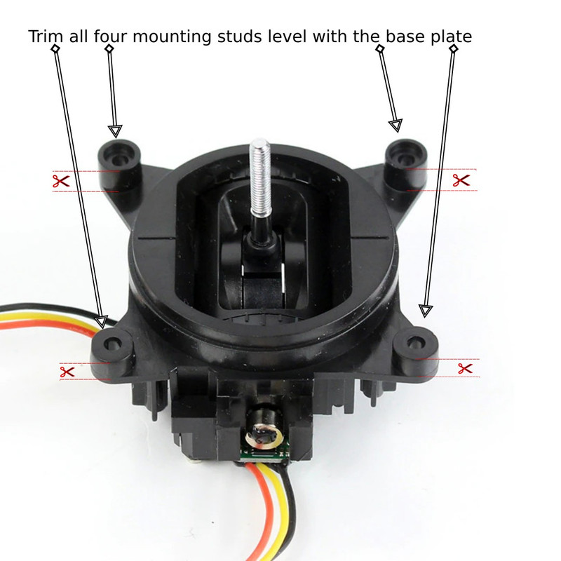
Before mounting the new gimbals it was necessary to trim down the mounting studs on the gimbals to be level with the base plate.
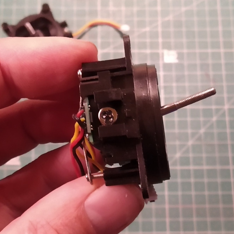
After trimming:
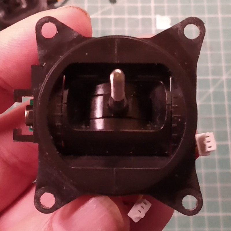
Once the gimbal studs have been trimmed the I reamed out the holes in the mounting adapter plate to 2.5mm and the holes in the brackets to 2.0mm. I then temporarily test fitted the brackets into the holes in the mounting plate. Ideally they should be a tight fit. I removed the brackets again and fitted the new gimbal into the adapter plate. The holes in the gimbal are slightly offset and do not line up exactly with the holes on the mounting plate, but the studs on the mounting brackets are also offset to compensate. I Installed the two brackets, fitting the studs through the holes in the gimbal and into the holes in the mounting plate. The gimbals were then ready to be screwed in as a direct replacement for the old gimbals. For more details see the
thingiverse page.
Before installing the gimbals I removed the battery and then removed the eight screws from the rear of the transmitter. The screws are different lengths, so I was careful to note where each screw belonged. Once the screws were removed I carefully prized the back off the case.
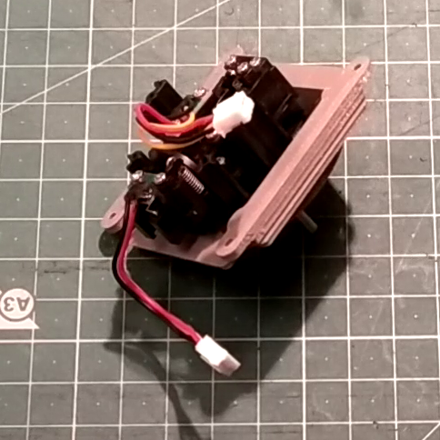
Before removing the old gimbals I released the two plugs that connected each gimbal to the circuit board, making sure I didn't pull on the wires. I then removed the four screws at the corners of each gimbal that secured it to the front of the transmitter.
In order to connect the new gimbals I had to change the connectors. I believe the connectors required are JST PH 2.0mm 3-pin connectors. I chose to crimp new connectors on to the gimbal wires although the wires were only just long enough. Alternatively, connectors with pre-crimped with silicone insulated wires are available from sites such as eBay and could be used to extend or replace the existing wires. Another choice would be to salvage the connectors and wiring from the old gimbals.
I discovered that the wiring on the new gimbals was misleading. The red lead was actually ground (0v), and the black lead was positive Vcc and required a voltage supply of between +2.5v and +3.5v. The yellow lead carries the output signal. Fortunately, the 9XR Pro provides 3.3v to the gimbals which is ideal. I checked which pins where connected to ground on the transmitter by testing continuity to the 0v and 3.3v test points on the transmitter control board and found that the left pin on each connector was 0v and the right was 3.3v. The middle pin is the signal.
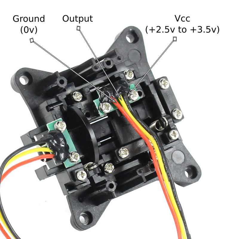
Accordingly, I connected the red (ground) wire to the left 0v pin, the yellow (signal) wire to the middle pin, and the black (Vcc) wire to the right 3.3v pin. This worked for me but anybody attempting to repeat my modification should make their own tests.
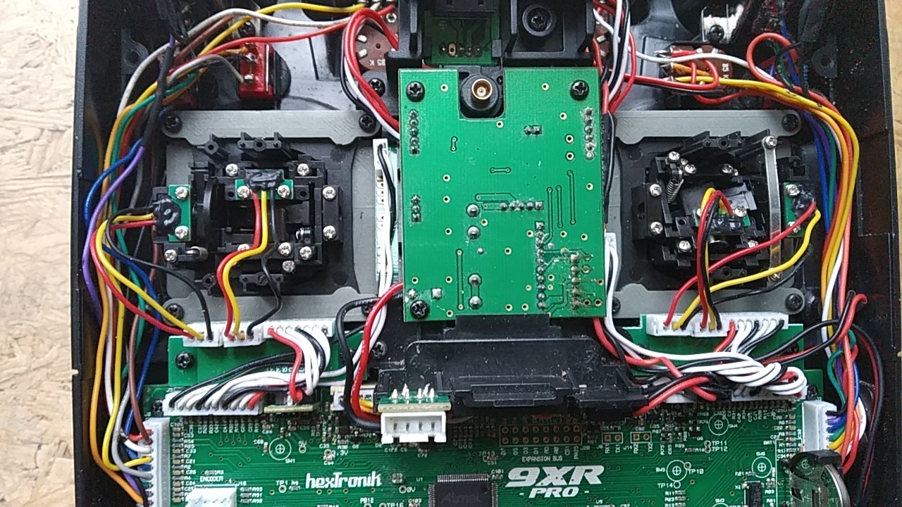
I reinstalled the gimbals using the original screws, being careful not to trap any of the wires while doing so. I then refitted the back of the case, again being careful avoid crushing any of the wiring or the antenna cable, and reinstalled the eight screws.
When I replaced the battery and powered the transmitter on I discovered that horizontal movement of the left stick, and vertical movement of the right stick were both reversed. As I fly mode 2, this meant that my rudder and elevator were both reversed.
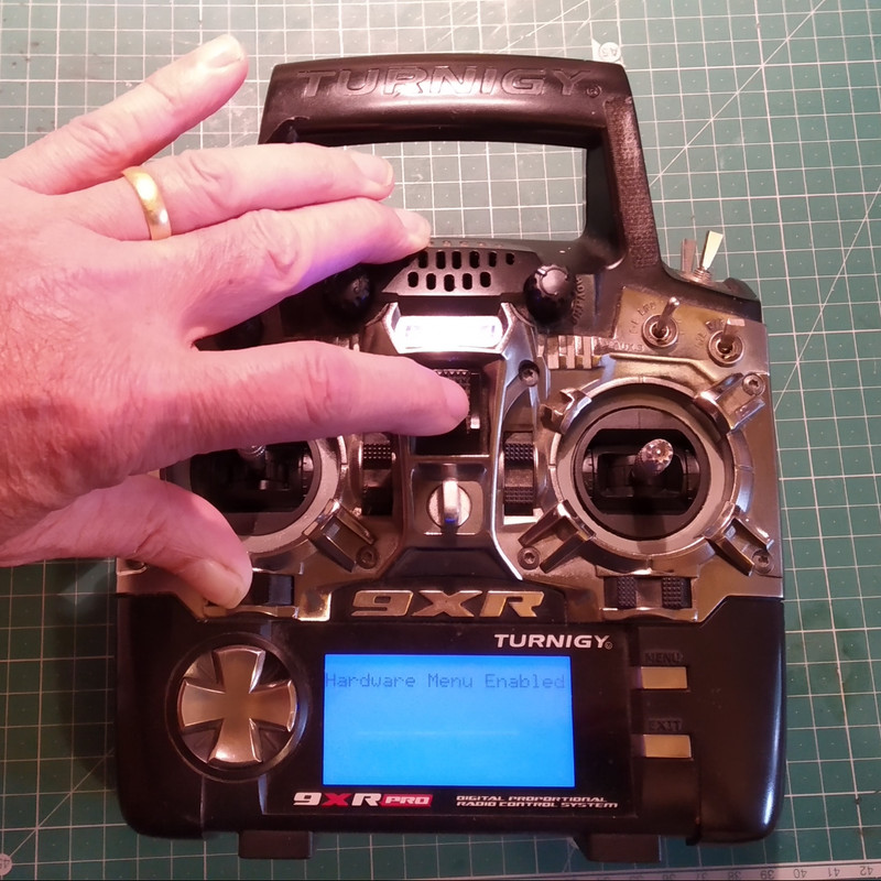
Since I have erSkyTX (erSky9x) installed on my transmitter, I was able to correct this in the Radio Setup/Hardware menu. To enable the hardware menu I held the left horizontal trim button button down to the left as I powered on the transmitter.
I set the first option on the hardware menu "Filter ADC" to DSMP. I then scrolled to the final item on the last page and labelled "Stick Reverse". I clicked Menu to select the item and then used the left and right keys until the first and third stick representations displayed highlighted in inverse.
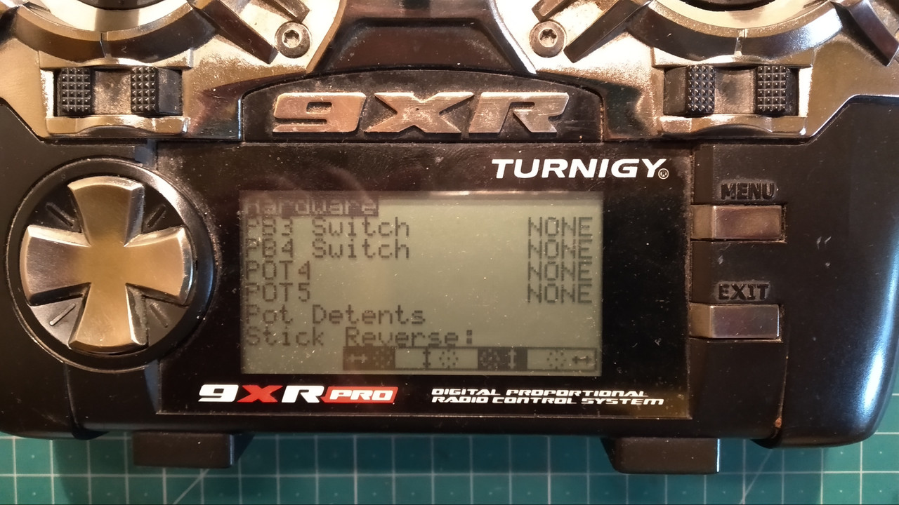
This corrected the issue. After running Radio Setup/Calibration the transmitter worked perfectly with the new gimbals.
As far as I could tell there is no equivalent way of reversing the stick movement if you are using openTX, short of recompiling the source code. It is, however, possible to instead modify the gimbals by rotating the sense magnets by 180 degrees. If anybody is interested I will post how to do this.